
Gears are machine elements that rotate and transmit torque from one shaft to another. A multitude of gear types is employed in machines, wherein, they work in unison to ensure that the entire mechanism runs smoothly. In this article, we will look at how gears work along with the different types of gears used in machines.
Meshing of Gears
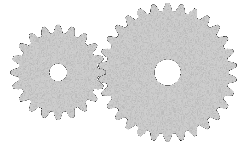
One gear’s teeth are fitted between the teeth of another gear in a process known as gear meshing. A gear train is made up of two or more gears that mesh and transmit power from one shaft to another. The design of the train employed in a certain application is determined by the gear ratio necessary, as well as the relative position of the shaft axes.
Why Do We Need Gears?
Gears are an extremely important device for transmitting rotation from one axis to another. Therefore, gears can adjust the output speed of a shaft. Assume you have a motor that rotates at 100 revolutions per minute and you only want it to spin at 50. A gear system can be used to reduce the speed so that the output shaft rotates at half the engine speed.
Furthermore, gears are widely utilized in high-load circumstances because their teeth allow for finer, more discrete control of a shaft’s movement and force. For example, if the second wheel in a set of gears has more teeth than the first, it turns slower but with more force than the first. Gears also offer an edge over most pulley systems in this regard.
When two gears mesh, the second spins in the opposite direction. For example, the gearbox located in the centre of the rear axle of a rear-wheel-drive vehicle employs a cone-shaped bevel gear to shift the driveshaft’s power through 90 degrees and turn the back wheels.
How Do Gears Work?
The gear wheels function similar to a regular wheel, the only difference is that the gears have teeth cut around the edge to prevent them from slipping. However, because a wheel is essentially a lever, a pair of wheels in contact with one another is equivalent to a pair of levers that are touching each other.
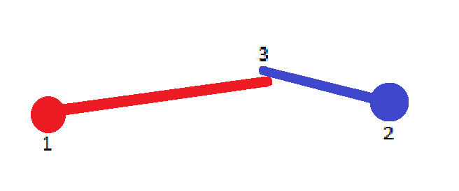
Thinking of gears as levers can explain how they work. Assume you turn the axle at point 1. Because it is acting as a lever, the bar connecting points 1 and 2 moves faster and with less force at point 2. Point 1 would then turn with less speed and greater force. If you turn at point 1 instead, you obtain more speed and less force at point 2.
Putting everything together, we apply a certain force and speed at point 1. At point 2, the red bar may provide four times the speed and a quarter of the force. But the blue bar will work the other way, at maybe half the speed and double the force. As a result, when we reach point 3, we have twice the speed but half the force that we had at point 1. That’s what we’d expect from a pair of gear wheels where one (blue) is twice the size and has twice as many teeth as the other (red).
For a more detailed explanation of how a gear work you can watch the video below.
Terminologies of a Gear
Before you start working with gears, you need to be familiar with a few terminologies, mentioned below.
Teeth
It refers to the jagged pieces protruding outward from the perimeter of the gear. A tooth transmits rotation to other gears. A gear’s tooth count must be an integer. Only when the teeth of two gears mesh and have the same profile do they transfer rotation.
Axis
This is the axis of revolution of the gear, where the shaft passes through.
Pitch Circle
This is the circle that defines the gear’s “size”. In other words, if the two gears were instead two discs driven by friction, the pitch circle would be the circumference of those discs. Two gears must have pitch circles that must be tangential in order for them to intermesh.
Pitch Diameter
The pitch diameter is the working diameter of the gear. It is also known as the pitch circle diameter. The pitch diameter can be used to calculate how far apart two gears should be, using the following formula: The distance between the two axes is equal to the sum of the two pitch diameters divided by two.
Diametral Pitch
The Diametral pitch is calculated as the number of teeth divided by the pitch diameter. To mesh, two gears must have the same diametrical pitch.
Circular Pitch
The distance measured along the pitch circle from one spot on one tooth to the same location on the adjacent tooth is known as the circular pitch. This measurement helps ensure that the length is correct.
Gear Module
The gear module formula is, the circular pitch divided by pi. Because it is a rational number, this value is considerably easier to manage than the circular pitch.
Pressure angle of a gear
This is the angle formed by the line defining the radius of the pitch circle and the point at which the pitch circle contacts a tooth, as well as the line tangent to that particular tooth at that point. The pressure angles that are commonly used are 14.5, 20, and 25 degrees. Pressure angles influence how the gears interact and how the force transfers along with the tooth. Meshing requires two gears to have the same pressure angle.
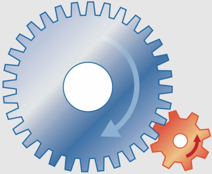
Driver and Driven Gear
Driver gear is the gear that transmits shaft power, while driven gear is the one that receives power. To generate a mechanical advantage, the number of teeth on the driver and driven gears are frequently different.
Gear Ratio
The gear ratio refers to the number of teeth of the driven gear divided by the number of teeth of the driver gear.
Types of Gears
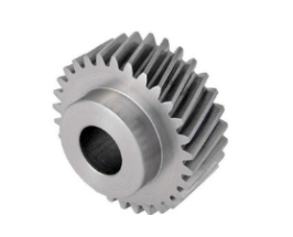
Spur Gears
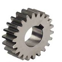
One of the most common forms of precision cylindrical gears are spur gears. These gears have a straightforward construction with straight, parallel teeth arranged around the circumference of a cylinder body with a central bore that fits over a shaft.
The gear is machined with a hub that widens its body around the bore without modifying the gear face. In addition, the central bore can be broached to accommodate the spur gear on a splined or keyed shaft.
Spur gears are employed in mechanical systems to transfer motion and power from one shaft to another. This transference can amplify torque, change the operating speed of machines, and allow for fine-tuned control of positioning systems. Because of their design, they are appropriate for lower-speed operations or operational areas with a higher noise tolerance.
Overall, spur gears are used in mechanical applications to multiply torque or raise or decrease the speed of a device by transferring motion and power from one shaft to another via a succession of matched gears.
Characteristics
- The most prevalent in most equipment
- Body of a circular gear
- Straight teeth cut or placed parallel to the shaft of the gear
- Used to set up parallel axes.
- Connected to gear racks or other spur gears
- High precision and efficiency
- Simple to produce
- It does not generate thrust force
- Capable of dealing with high speeds and loads
- Gear teeth are subjected to significant stress as a result of tooth design
- Noise production at high speeds
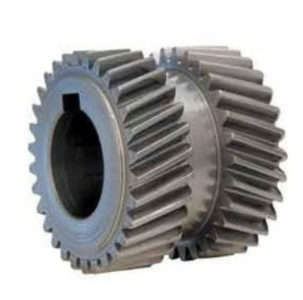
The Helical Gear
Helical gears are cylindrical gears that have sloping tooth tracks. They have a higher contact ratio than spur gears, are quieter and have less vibration. Furthermore, they can transmit a considerable amount of force.
Helical and spur gears are two of the most popular types of gears, and they can be employed in many of the same applications. Although spur gears are easy and inexpensive to produce, helical gears have several significant advantages over spur gears. A helical gear’s teeth are positioned at an angle relative to the gear’s axis and take the shape of a helix. This permits the teeth to gradually mesh, first with point contact and progressing to line contact as the engagement advances.
Less noise is another visible advantage of helical gears over spur gears, especially at medium to high speeds. Furthermore, with helical gears, numerous teeth are always in mesh, resulting in reduced strain on each individual tooth. This causes a smoother transition of forces from one tooth to the next, reducing vibrations, shock loads, and wear.
Characteristics
- Body of a circular gear
- Teeth are curled at an angle around the gear body
- Used to set up parallel axes
- Designs are available in both right-hand and left-hand orientations.
- There are single and double helical versions available
- Less impact loading and gradual tooth engagement
- Operation is quieter and smoother
- Capable of carrying heavier loads
- Reduced efficiency
- Higher design complexity equals higher manufacturing costs
- Presence of a thrust force in a single helical design, but not in a double helical design
The Dual Helical Gear
Double helical gears are a helical gear variation in which two helical faces are arranged next to each other with a gap between them. Each face has helix angles that are identical but opposing. Using a double-helical set of gears lowers thrust loads and allows for even more tooth overlap and smoother operation. In enclosed gear drives, double helical gears are typically utilised as the helical gear.
Herringbone Gears
Herringbone gears are extremely similar to double-helical gears, except there is no space between the two helical faces. They are often smaller than comparable double helical gears, making them appropriate for heavy shock and vibration applications. Because of the cost of production, herringbone gearing is rarely employed.
Rack and Pinion Gear
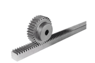
A rack is a flat gear with an infinite radius of the pitch cylinder. It contains a set of identically sized and shaped teeth cut at equal distances along a flat surface or a straight rod. The gear turns rotational momentum into linear motion by meshing with a cylindrical gear pinion. Straight tooth racks and helical tooth racks are the two primary categories of gear racks. It is feasible to link gear racks end to end by milling the ends of the gears.
Characteristics
- A gear rack and a cylindrical gear (pinion) form a pair
- Used to set up parallel axes
- Rotational motion is converted to linear motion and vice versa
- Simple design, simple manufacturing
- Capable of carrying heavier loads
- Transmission in one direction cannot continue indefinitely
- There is a lot of blowback between joined teeth
- Because of the tooth design, gear teeth undergo tremendous friction and stress
A Bevel Gear
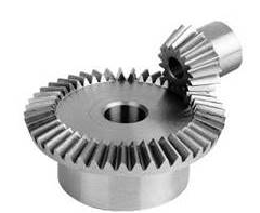
A bevel gear is a toothed rotating mechanical device used to transfer mechanical energy or shaft power between shafts that are perpendicular or at an angle. As a result, the shaft power’s axis of rotation shifts. Aside from this, bevel gears can increase or decrease torque while changing the angular speed in the opposite direction. A truncated cone represents a bevel gear.
Characteristics
- Cone-shaped gear body
- Used in the configuration of intersecting axes
- Straight, spiral, and Zerol tooth designs are available
- Straight: The most basic bevel gear design and the easiest to manufacture. Has a high impact, noise level, and stress
- Spiral: Progressive tooth engagement with less noise, impact loading, and vibration. Has a higher design complexity and production cost
- Zerol: Quieter and smoother than a straight bevel. It can rotate in both directions, unlike a spiral bevel.
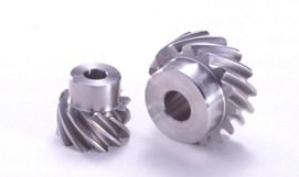
Spiral Bevel Gear
Spiral bevel gears have curved tooth lines. They outperform straight bevel gears in strength, efficiency, vibration, and noise due to their higher tooth contact ratio. Furthermore, because the teeth are curved, they generate axial thrust forces. They are, however, more difficult to make. The spiral bevel gear with zero twisting angles is known as a zero bevel gear.
Screw Gears
Screw gears are made up of two same-hand helical gears with a 45° twist angle on non-parallel, non-intersecting shafts. Because the tooth contact is a singular point, they have a low load-carrying capability and are not appropriate for high power transmission. Furthermore, because power is delivered by the sliding of the tooth surfaces, lubrication is essential when utilising screw gears.
Worm Gear
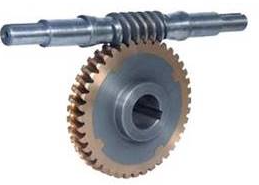
A combination of a screw form cut on a shaft along with the worm wheel which is the mating gear is termed a worm gear. Worm gears and worm wheels do not have to be cylindrical. In fact, its hourglass shape can boost the contact ratio, but it makes manufacturing more complicated.
Friction must be reduced due to the sliding contact of the gear surfaces. As a result, the worm is often made of hard material, whereas the worm wheel is made of soft material.
Characteristics
- A circular gear and a screw-shaped gear form a pair.
- This configuration is used for non-parallel, non-intersecting axes.
- Gear reduction and high gear ratios
- Operation is quiet and smooth
- Has a mechanism for self-locking
- Transmission efficiency is low
- Significant quantities of friction
For more gear types you can view the document given below.
Uses of the Different Types of Gears
Mentioned below are the various uses of some of the gears discussed in this article
Industries | Applications | Rexnord Products |
| Spur Gear | Food Beverage Forest Energy Automotive Unit handling | Small conveyors Farm machinery Planetary gear setsPackage handling equipment Automotive |
| Helical Gear | Cement Food Marine Energy Forest Beverage Mining Bulk material handling | Medium and large conveyorsMixersWater treatmentCrushersLarge pumps |
| Double Helical Gear | Mining Marine | Steam turbinesMillingShip propulsion |
| Herringbone Gear | Mining Marine | Steam turbinesMillingShip propulsion |
| Bevel Gear | Cement Beverage Mining Food Energy Bulk material handling | CrushersMedium and large conveyorsMixersWater treatment |
| Worm Gear | Food Beverage Forest Energy Automotive Unit handling | Small conveyors Package handling equipment Farm machinery |
Benefits of Gears
Gears have several benefits in the machines we use on a day to day basis. Some of them are as follows:
- With the use of gear trains, a high-velocity ratio can be obtained in a little amount of area.
- Gears are utilised in the transmission of high-frequency signals.
- They are used to transmit motion over shafts with a limited centre distance.
- As gears are mechanically sturdy, heavier loads can be lifted.
- They are utilised for substantial speed reductions and torque transmission.
- The only maintenance a gear requires is frequent lubrication.
- We can transmit motion between non-parallel crossing shafts using gear sets.
- They are utilised for a positive drive, which keeps the velocity ratio constant.
- Because they have a long life, the gear system is quite compact.
Drawbacks of Gears
Despite the numerous above mentioned benefits, gear systems do have some drawbacks. They are as follows:
- They are not ideal for high speeds.
- In the event of high loading, some parts of the machine may be irreversibly destroyed due to the engagement of toothed gear wheels.
- They are ineffective at conveying motion over long distances.
- They have no wiggle room.
- The operation is noisy.
Gear Failure
Gear failures due to wear can occur for a variety of causes. The following are some of the more common causes of gear failure.
Moderate wear
This sort of wear leaves contact patterns that reveal the metal in the addendum and dedendum area has been impacted. It is often caused by insufficient lubrication, although it can also be caused by contamination in the lubricant.
Excessive wear
This refers to wear that has persisted until a large amount of material on the surfaces has been impacted. With extreme wear, you may notice pitting on the surface, which is often caused by failing to detect the first signs of wear early enough.
Frosting
This problem frequently manifests itself in the dedendum area of the driving gear. The wear pattern has a frosted effect due to the numerous micro pits on the surface. The frosting is a typical problem that occurs when the lubricating coating is broken away by the heat.
Abrasive wear
Signs of abrasive wear in gears may appear as radial scratch marks, grooves, or some other indication that contact is an issue. Foreign bodies in the lubricant are one of the most typical causes of abrasive wear. It is frequent in new systems prior to the filter cleaning system.
Corrosive Wear
The surface of the gear deteriorates due to chemical activity, such as acid, moisture or additives in the lubrication fluid. As the oil degrades, the chemicals in the lubricant assault the surfaces. It usually results in uniform, fine pitting.
Breakage
The entire tooth or a portion of the tooth may break away. It frequently leaves traces of the focal point of the fatigue that caused the break, which can be caused by a variety of conditions, including high stress or severe dental loads.
Final Thoughts
This article gives a fundamental overview of gears, including the various types available, their applications, and reasons for failure. As gears are essential to all machinery in today’s world, when a problem with the gears occurs, it is vital to assess whether a rebuild, upgrade, or replacement is the best option. Furthermore, to prevent failure proper upkeep and lubrication are necessary. Visit Podium School for more information.
FAQs
Which of the following gear types have inclined teeth?
Helical gear is a form of gear with inclined teeth that has a far greater ability to carry weight than spur gear of the same size.
What is the most frequently used gear?
Spur gear is the most frequent form of gear used in industry or any machine since it may be utilised at any speed.
A spur gear has what kind of teeth?
Straight or parallel teeth are commonly utilised in spur gears.
What is the distinction between a gear and a pinion?
The primary distinction between a gear and a pinion is that a gear is used as a driver, whilst a pinion is used as a driven.
Share with your friends


