Transformers transmit electric energy from one alternating current circuit to another by increasing or decreasing the voltage. From toy trains to power grids, there are many applications of a transformer. Let’s look at the types of transformers, and their working in more detail.
- Working Principle of Transformer
- Components of a Transformer
- Types of Transformers: Based on Design
- Different Types of Transformers: Based on Voltage
- Types of Transformers: Based on Core Material
- Types of Transformers: Based on Winding Arrangement
- Types of Transformers: Based on Cooling Method
- Applications of a Transformer
- Conclusion
- FAQs
Working Principle of Transformer
A transformer’s operation is straightforward. It works on the principle that mutual induction allows the transfer of electrical energy across circuits using two or more coils.
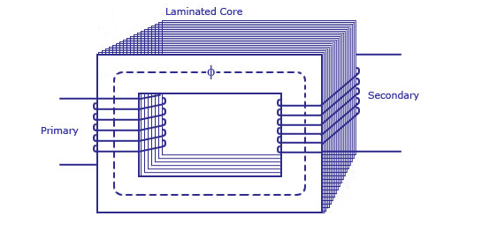
The image depicts the primary and secondary coils of an electrical transformer. The core is laminated with strips that have thin gaps in between them, which run across the cross-section of the core. The transformer generates an electromotive force from the alternating flux set up in the laminated core due to the coil that connects to a source of alternating voltage (primary coil). The primary coil is linked to the secondary coil, which in turn, produces a mutual induced electromotive force. With the help of Faraday’s laws of Electromagnetic Induction, this electromotive force is written as:
e=M*dI/dt
After closing the second coil circuit, current passes through it and electrical energy magnetically transfers from the first to the second coil. As the first coil receives an alternating current source, we refer to it as the primary winding. On the other hand, because energy is extracted from the second coil, it is called the secondary winding.
In summary, a transformer performs the following operations:
- Transfers electric power from one circuit to another.
- Transfers electricity without any change in frequency.
- Uses the electromagnetic induction method to transfer electricity.
- Links the two electrical circuits with mutual induction.
For a better understanding of the working principle of a transformer, you may watch the video linked below.
Components of a Transformer
A transformer’s primary components are as follows:
Core
The core of the transformer functions as a support for the winding. It also provides a low resistance channel for the flow of magnetic flux. To decrease energy losses, a core consists of a laminated soft iron core. Furthermore, parameters such as operational voltage, current, and power determine the core composition. A point to note is that the core diameter is related to the amount of copper lost and inversely proportional to the amount of iron lost. (For more information, read the FAQs)
The Winding
Windings are the copper wires that coil around the transformer core. The high conductivity of copper minimizes the loss of energy because of the principle: “when the conductivity increases, resistance to current flow decreases”. Furthermore, the high ductility of copper, which allows for the metal to be moulded into thin wires, is a desirable trait as well.
Windings are classified into two categories.
- Primary Winding: These are the set of coils that obtain supply current.
- Secondary winding: These are the set of coils that release the current output.
Insulation
Transformers require insulation to separate windings as well as prevent short circuits. Therefore, insulating agents have an impact on a transformer’s durability and stability. A transformer employs the following materials as an insulating medium:
- Oil
- Tape
- Wood-based lamination
Types of Transformers: Based on Design
The arrangement of the main and secondary coils around the laminated steel core varies across transformer types. This gives rise to two types of transformers based on their design:
Core Transformers
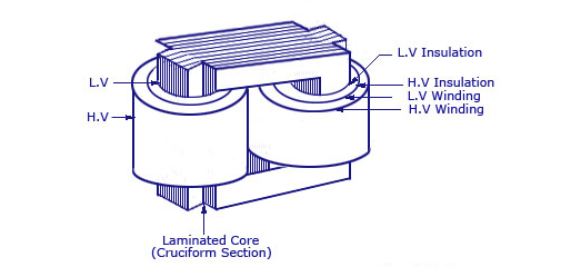
In this transformer, windings coil around a large portion of the core. These coils are form-wound and cylindrical in shape. On the other hand, the core is rectangular. Additionally, the circular or cylindrical coils are such that they fit over a cruciform section of the core.
Circular cylindrical coils provide a significant advantage in terms of mechanical strength. These coils consist of multiple layers, each of which may be insulated from the others using materials such as paper, cloth, micarta board, and so on. The image below depicts the typical configuration of the core-type transformer with regard to the core.

Shell Transformers
A significant amount of windings cover the core in shell-type transformers as well. Furthermore, the coils are form-wound and look like multilayer discs coiled in the shape of pancakes. Paper or other insulating materials cover each of these discs. In other words, the entire winding consists of stacked discs with insulating intervals between the coils.
A transformer of this type might take the form of a basic rectangle or a scattered form. The diagrams below depict both designs:


A robust, stiff bracing mechanically braces the transformer cores and coils. This helps to minimise device movement as well as protect the gadget from insulation damage. A well-braced transformer does not make any humming noises when operating. Therefore, there is an observable decrease in vibration.
The choice between the core and shell transformer depends on cost because both types can produce equivalent results. However, for high-voltage applications or multi-winding designs, most manufacturers favour shell-type transformers because they possess a coil of greater mean length as compared to the core types.
Different Types of Transformers: Based on Voltage
The transformer is classified into three types based on the voltage level: Step-Down, Step-Up, and Isolation Transformer.
Step-Down Transformer
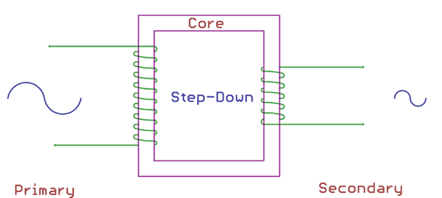
A step-down transformer reduces the voltage across the secondary output. This process relies on the ratio of the primary and secondary windings. The number of windings across the primary side of a step-down transformer is more than the number of windings across the secondary side. As a result, the total ratio of primary windings to secondary windings is always greater than one.
Step-down transformers find uses in electrical distribution systems that operate at very high voltages to offer less loss as well as a cost-effective solution for long-distance power delivery requirements. In addition, power adapters and cell phone charger circuits use these transformers.
Step-Up Transformer
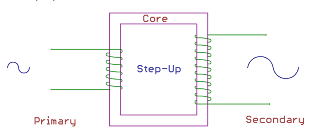
The step-up transformer is the inverse of the step-down transformer. Therefore, a step-up transformer increases the low primary voltage to a high secondary voltage. Similar to step-down transformers, this process relies on the ratio of the primary winding to secondary winding. This ratio stays less than one for the step-up transformer. That is, the number of turns in the secondary winding is more than the number of turns in the primary winding.
Step-up transformers are used in stabilisers, inverters, and other appliances where a low voltage is transformed into a much greater voltage.
Isolation Transformers

These transformers do not convert voltage levels. This implies that an isolation transformer’s primary and secondary voltages are always the same. This is because the main and secondary winding ratios are always equal to one. In other words, the number of turns in the isolation transformer’s main and secondary windings are the same.
Isolation transformers find are used as an isolation barrier. Furthermore, people use it to ensure safety and to cancel noise transmission from primary to secondary voltage or vice versa.
Types of Transformers: Based on Core Material
The power and electronics domains employ several types of transformers These transformers differ in their core materials. The types of core materials as are follows:
Transformer with an Iron Core

In this design, the primary and secondary coils wrap around the core former. The coil former is then installed in soft iron core plates. A variety of core plates are available on the market, depending on the core size and form. Some of the most commonly available shapes include E, I, U, and L. Iron core transformers are typically larger in weight and design.
Transformer with Ferrite Core

Because of its high magnetic permeability, transformers may employ ferrite cores. Therefore, in high-frequency applications, this kind of transformer has very low energy losses. As a result, switch-mode power supplies (SMPS), RF-related applications, etc, employ ferrite core transformers. Ferrite core transformers are also available in a variety of forms and sizes, depending on the application. The E core shape is the most frequent used ferrite core transformers.
Transformer with a Toroidal Core
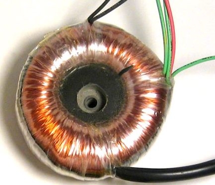
Toroids are core materials with ring or doughnut shapes, that people use extensively for enhanced electrical performance. Toroidal core transformers make use of toroid-shaped core materials made of iron or ferrite. The leakage inductance is very low due to the ring form, and the inductance and Q factors are quite high. Furthermore, the windings are relatively short, and the weight is significantly less than that of standard transformers of the same rating.
Transformer with an Air-Core
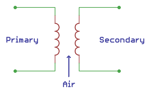
The core material of an Air-Core transformer is not a physical magnetic core. Instead, air forms of the entirety of the transformer’s flux linkage. The primary coil of an air-core transformer is fed with alternating current which creates an electromagnetic field surrounding it. Then, when a secondary coil is put inside the electromagnetic field, the secondary coil is induced with a magnetic field. This field is then utilised to power the load, according to the Faraday’s law of Electromotive Induction. However, when compared to physical core materials such as iron or ferrite core, air-core transformers have low mutual inductance.
Air-core transformers find uses in portable electronics and radiofrequency applications, as it is incredibly light in weight because of the lack of a solid core substance. Wireless charging systems also use a properly tuned air-core transformer. Here, the primary windings are built inside the charger and the secondary windings are built outside it.
Types of Transformers: Based on Winding Arrangement
Transformers can also differ based on the winding arrangement.
Transformer with Auto Winding
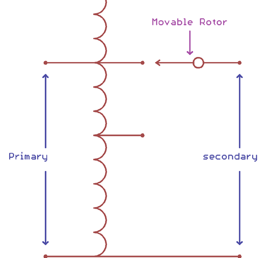
Here, the auto is not an abbreviation for Automatic. Instead, it talks about the self or a single coil. This coil has two parts: primary and secondary. The location of the centre tap node determines the primary and secondary ratios, which affect the output voltage.
Until other transformers, the primary and secondary windings in an auto-winding transformer are not fixed. Instead, they are linked in series, and the centre tapped node can be moved.
The VARIAC, an instrument that generates variable alternating current from a steady alternating current input, is the most typical use of an auto-winding transformer. Power transmission, as well as distribution applications, are some other common applications of this type of transformer.
Types of Transformers: Based on Cooling Method
Oil Filled Self-Cooled Type
The oil-filled self-cooled variety includes small as well as medium-sized distribution transformers. In such transformers, a welded, oil-tight steel tank with a steel lid contains the complete winding and core. Once the core is placed, the tank is filled with pure, high-quality insulating oil. The oil aids in the transfer of heat from the core as well as the windings to the casing, from where it radiates out into the environment.
Tanks for lower sized transformers normally have a smooth surface. However, larger-sized transformers require a larger heat radiation area, without affecting the cubical capacity of the tank. A corrugated case can help achieve this.
Air Blast Cooled Type
Transformers with voltages less than 25,000 volts use this type of cooling method. Here, a thin sheet metal box, open on both ends, covering the transformer. This allows air to flow from the bottom to the top and cool the system.
Oil-Filled Water-Cooled Type
Because the oil-filled self-cooled technology is quite expensive, an oil-filled water-cooled type is used to considerably lower the cost of building huge transformers. Insulating oil covers both the windings and the core, in the same manner as in an oil-filled self-cooled type. The only difference is that cold water circulates through a cooling coil installed at the oil’s surface. This water carries out the heat generated by the transformer. The most significant advantage of such a design is that such transformers do not require any housing other than their own, thus, significantly cutting the costs. Another benefit is that these transformers require maintenance as well as upkeep only once or twice a year. Generally, transformers used in high voltage transmission lines utilize this cooling type.
Applications of a Transformer
A Transformer has many uses. Some of them are as follows:
- A transformer helps obtain the desired voltage level. Step-up transformers raise the voltage, while step-down transformers decrease it.
- A transformer can change the value of a capacitor, inductor, or resistance in an alternating current circuit. As a result, it functions as an impedance transferring device.
- Transformers can electrically disconnect two circuits.
- A transformer is employed in impendence matching.
- Several electrical measuring devices such as ammeters, voltmeters, relays, etc, use transformers.
- Rectification requires transformers. Rectification refers to the process of converting alternating current to direct current. Furthermore, it is required for high voltage transmission. A mobile charger is the greatest example of a rectifier.
- Voltage regulators, as well as voltage stabilisers, use transformers.
- Transmission and distribution of power also require transformers.
Conclusion
People generally use a transformer to obtain the needed voltage level. In addition, it may also be used electrically to isolate two circuits. Electricity transmission and distribution also require transformers. Thus, it is not wrong to say that a transformer is a crucial component of everyday life and cost-effective electricity transmission. We hope that this article has helped you understand the working and types of transformers.
FAQs
What causes transformers to hum?
The magnetic flux travelling through the transformer core fluctuates continually, causing the core to expand and shrink. The continual expansion and contraction of the steel core inside the transformer cause transformers to hum. The quantity of flux, determined by the applied voltage as well as the number of turns of the transformer coils, controls the core expansion.
What is the definition of core loss in transformers?
Core losses, also known as iron loss, are losses that occur in the transformer’s laminated metal core. The load does not affect these losses. Instead, they stay constant for any given transformer. Variations in the magnetization of the core during the alternating current supply cycle are the primary reason for these core losses. Core loss consists of eddy current loss and hysteresis loss. After charging the transformer, these two losses remain constant.
What is copper loss in transformers?
Copper loss refers to the heat created by electrical currents in the conductors of transformer windings. Copper losses, as well as core losses caused by induced currents in nearby components, are undesired energy transfers.
How to reduce core loss?
Cores consist of higher-quality steel to prevent core losses. Furthermore, using laminated cores, particularly thinner core laminations, can also aid in improving transformer efficiency by lowering core losses.
What exactly are eddy currents?
A fluctuating magnetic field creates circulating currents in a conductor. These currents are known as eddy currents. Eddy currents travel in planes perpendicular to the magnetic field, in closed loops, and within conductors. Furthermore, these currents increase the temperature of the transformer core.
Refer to the documents given below for a detailed understanding of eddy currents as well as eddy current losses.
Our homes use which type of transformers?
Distribution networks use step-down transformers to convert high grid energy to a low voltage that residential appliances can utilize.
What is the difference between a transformer and an autotransformer?
A standard transformer contains one primary winding as well as a secondary winding. To perform both duties, an autotransformer has a single tapped winding.
What is the difference between an instrument and a power transformer?
Power transmission, as well as distribution, use a power transmitter to step up or step down a voltage level. On the other hand, in a circuit, an instrument transformer is used to monitor voltage or current. Instrument transformers include potential as well as current transformers.
What exactly is hysteresis loss?
Due to hysteresis, a significant amount of energy is wasted in the transformer core. This is produced by a lag in the decrease of magnetic flux in the core when the magnetic field diminishes as the alternating current cycle swings from positive to negative maximum voltage.
What exactly is the purpose of a Buchholz relay?
A Buchholz relay is a safety device that detects flaws inside a transformer. It is a relay that is activated by oil. The device is powered by the avalanche of gases produced by transformer oil breakdown during faults.
Transformers use Faraday’s Laws of Electromagnetic Induction. What are they?
Faraday’s Laws of Electromagnetic Induction consist of two rules. The first rule defines emf induction in a conductor, whereas the second law quantifies the emf created in the conductor.
The following is Faraday’s first law of electromagnetic induction:
- When a conductor is put in a changing magnetic field an electromotive force is produced. When the conductor circuit is closed, a current, known as induced current, is induced.
The video linked below will explain Faraday’s first law of Electromagnetic Induction in detail.
Faraday’s second rule of Electromagnetic Induction mentions that:
- The induced emf (electromotive force) in a coil is equal to the flux linkage rate of change.
Refer to the video linked below for a more detailed explanation.
What is overheating fault?
One of the most typical problems with transformers is the rise in temperature. There are several reasons why this may occur:
- The cooling fans are not functioning correctly. (Inspect the fans and oil pumps carefully)
- The radiator is filthy. (Examine it and get rid of any dirt, dust, or plastic bags)
- Overcurrent. (Verify the transformer’s current and, if required, lower loads to match its rated current)
- A hot day. (The temperature of the surrounding atmosphere has an effect on the transformer temperature. Increase the number of cooling stations if this is the case)
- Low amount of oil. (The major purpose of the oil is to cool the transformer, check the level, and replenish the oil. However, keep an eye out for any leaks)
What is the transformer formula?
The transformer formula is denoted as:

Where,
| Vp | The primary voltage |
| Vs | The secondary voltage |
| Np | The number of turns in the primary coil |
| Ns | The number of turns in the secondary coil |
Share with your friends


